The Kernel DevKit includes 12 modules, but it is designed for complete flexibility. By utilizing a soft-cap interface, you can tailor your hardware configuration to your specific experimental needs. This customizable design allows you to punch mounting points and install optical modules exactly where your research requires, ensuring optimized sensor density and placement.
Required Materials
The following materials are not supplied by Kernel.
| Item | Recommendation / Notes |
| Reference Headform | The included stand works, but 3D-printed NIOSH headforms are suggested for precision. |
| 2mm Wetsuit Cap | Example here |
| Sewing Supplies | Scissors, seam ripper, needle, and bonded nylon T90 thread |
| Measuring Tape | For precise layout and alignment |
| Marker | White or silver permanent markers are recommended for visibility on black neoprene. |
| Module/EEG Position Guides | See the Position Guides section. |
| Fabrication Tools | A laser cutter is preferred; however, most low-cost filament 3D printers are sufficient. |
For EEG Installation
- Hole Punch: 6mm or 1/4 inch (example here)
- Impact Surface: A hammer and sturdy work surface (if using a manual punch).
- Electrode Seating Tool: Use the Kernel-supplied tool for final assembly.
Cap Assembly - Optical Modules
Preparing Cap
1. Initial Modification
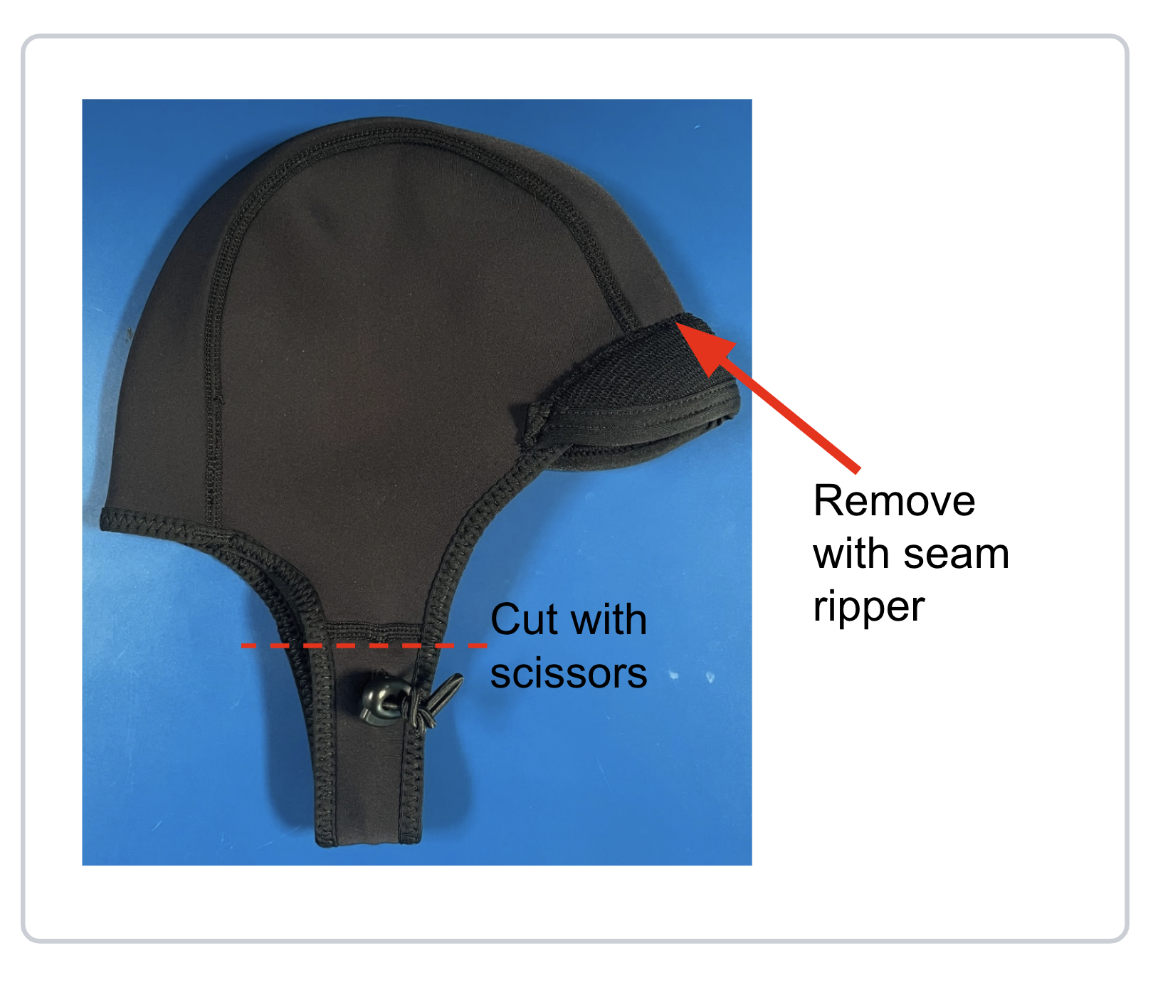
Select the appropriate wetsuit cap size for your subject. If your cap includes a brim or chinstrap, use a seam ripper to remove them completely, ensuring a flush surface for the modules.
2. Alignment & Marking
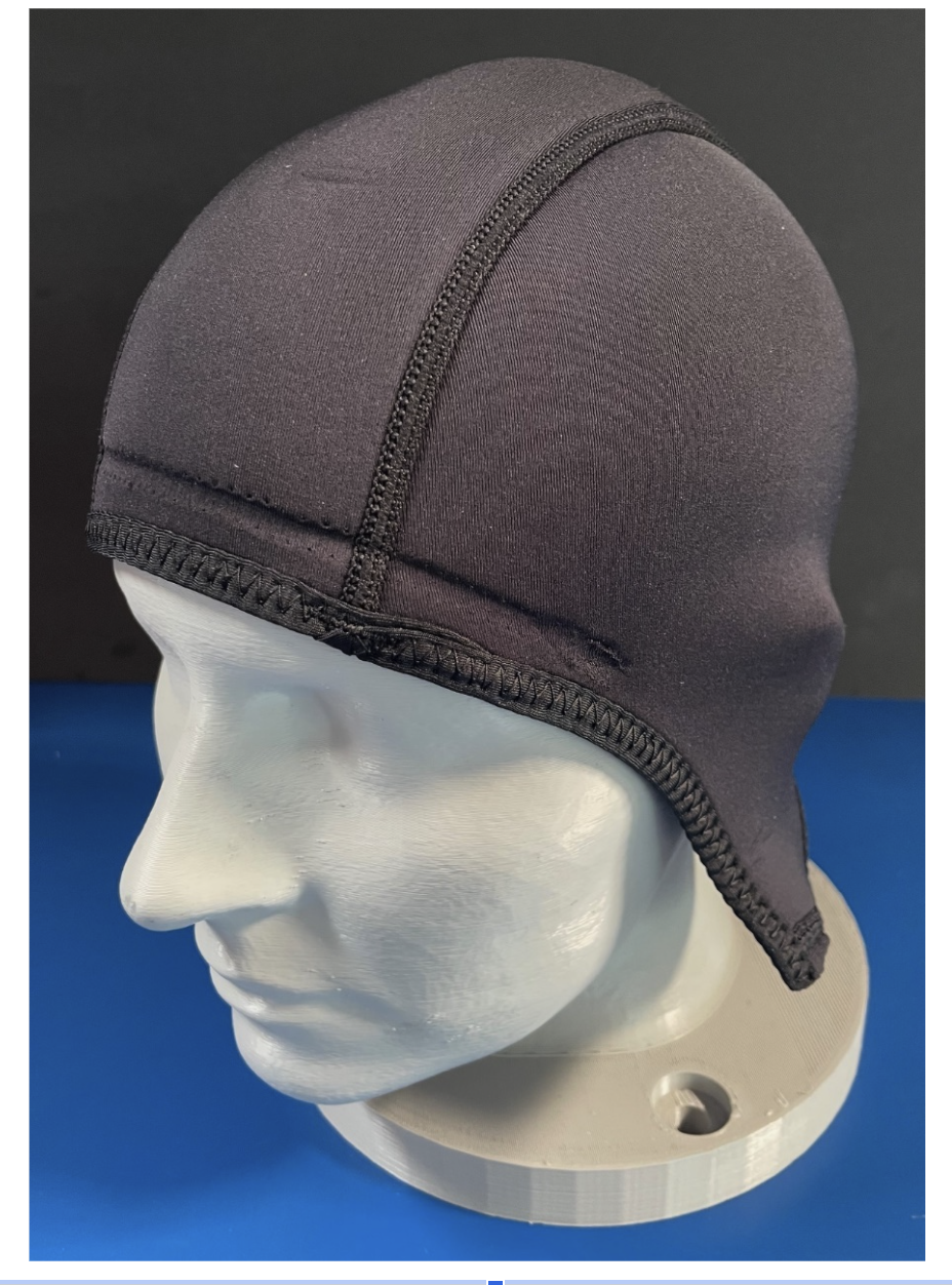
Mount the cap onto your reference headform (e.g., a 3D-printed NIOSH headform).
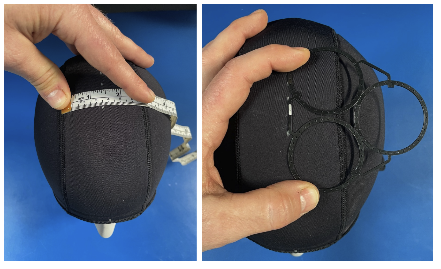
Mark a vertical centerline and a horizontal baseline to serve as your measurement anchors. Place your module guides onto the cap. If your guides feature straight edges, align them parallel to your datum lines to ensure symmetry.
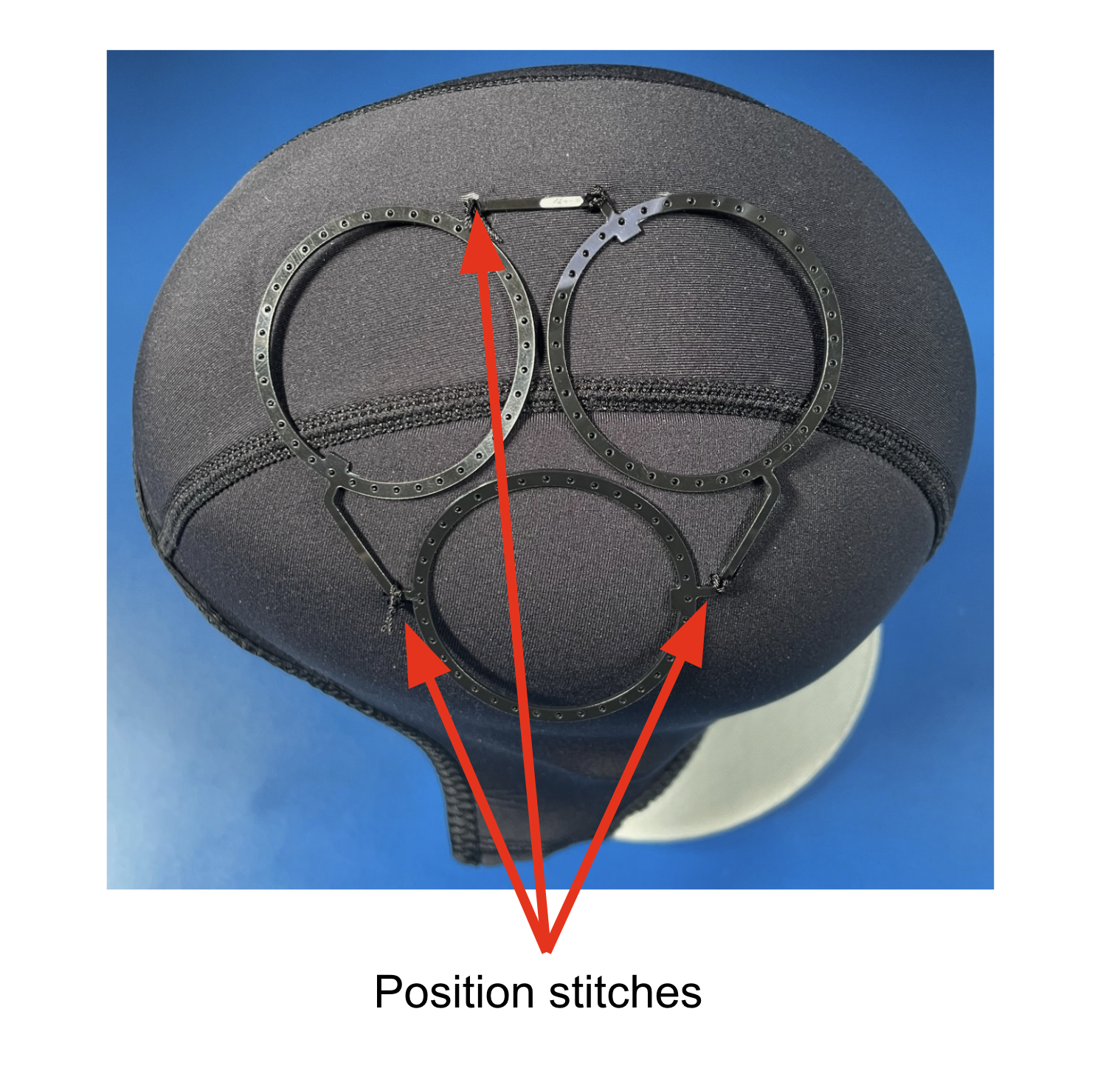
3. Securing the Guides
Do not sew the rings down yet. Instead, use a needle and thread to make 2–3 loose loops over the arms/connectors that join the rings together. This allows you to shift or rotate the guide slightly if the initial placement is off.
If using mirrored left/right patterns, tack-stitch both sides and verify alignment before proceeding to the permanent whip stitch.
For better precision, consider joining mirrored patterns in CAD before fabrication.
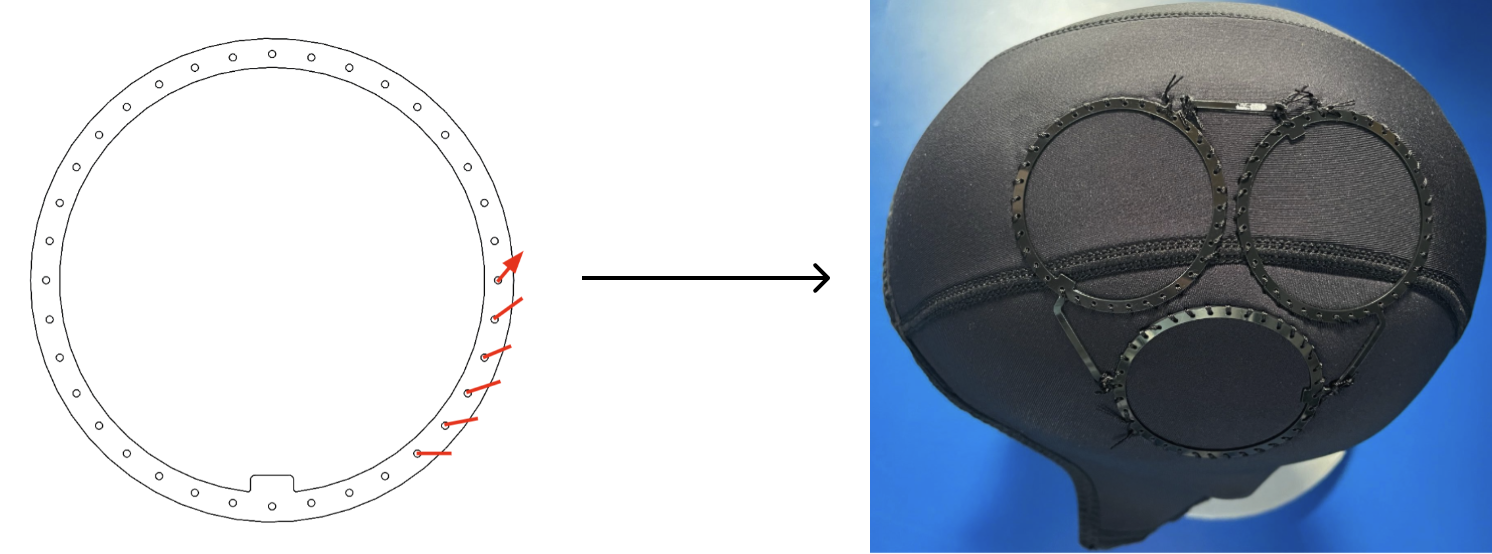
4. Permanent Whip Stitching
Once the position is finalized, apply a whip stitch around the entire outer perimeter of each module ring. This technique provides maximum stability and keeps the thread away from the interior of the ring, protecting it during the cutting process. Ensure stitches are tight; there should be zero movement between the guide and the neoprene when finished.
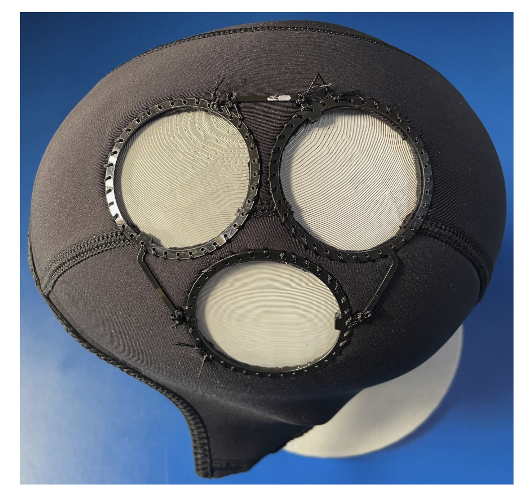
5. Excising the Sensor Ports
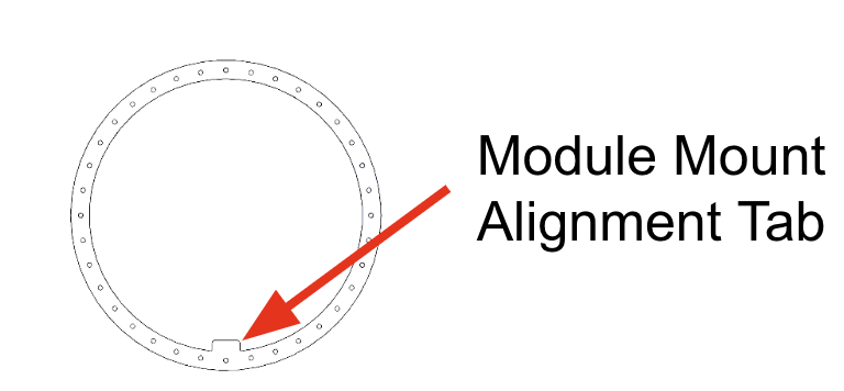
Using scissors or a precision hobby knife (e.g., X-Acto), carefully remove the neoprene from the center of each ring. Cut as close to the inside edge of the guide as possible. Use care not to nick the structural threads or the protruding alignment tabs of the guide.
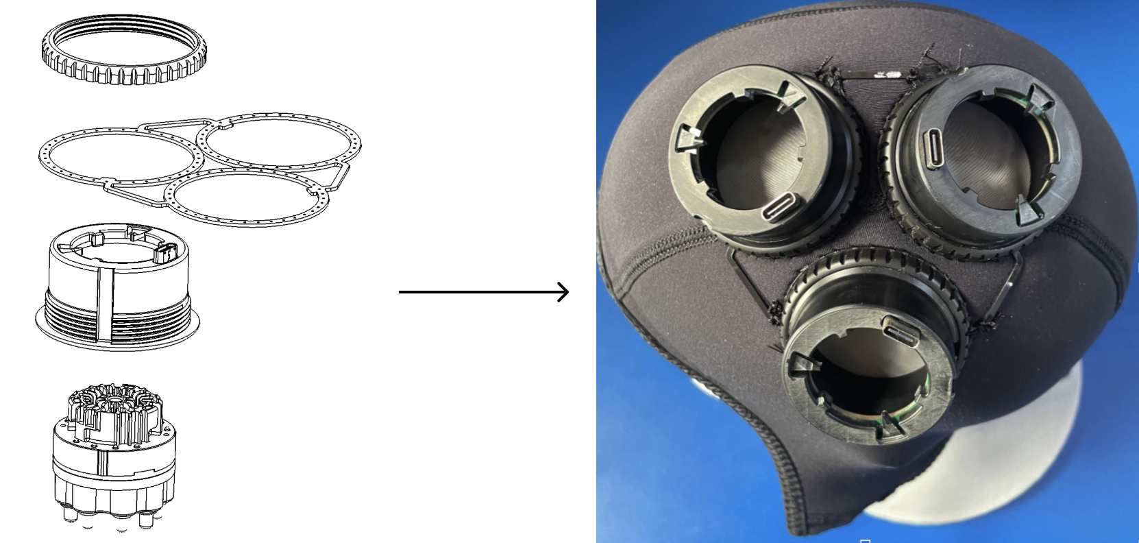
Installing Modules
Retrieve the module mounts provided by Kernel. From the inside of the cap, press each mount firmly into its corresponding position guide. Ensure each mount is seated completely and evenly against the guide.
Make sure each alignment tab is aligned with the notch in the module mount.

Finally, thread each module mount lock ring into place and hand-tighten (do not over-tighten).
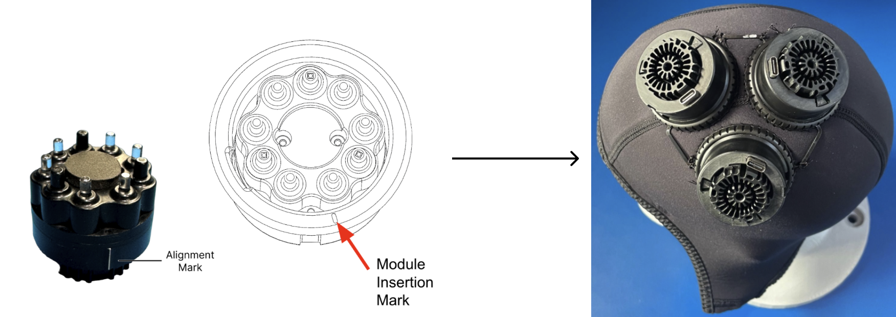
To install an individual module, locate the alignment mark on the module body and line it up with the insertion mark on the mount’s inside flange. Slide the module into the mount until it bottoms out.
To lock the module, rotate it 15° clockwise. You should feel a tactile "click" or a firm stop, indicating the module is locked and resistant to counter-clockwise movement.
Cap Assembly - EEG Electrodes
Preparing Cap
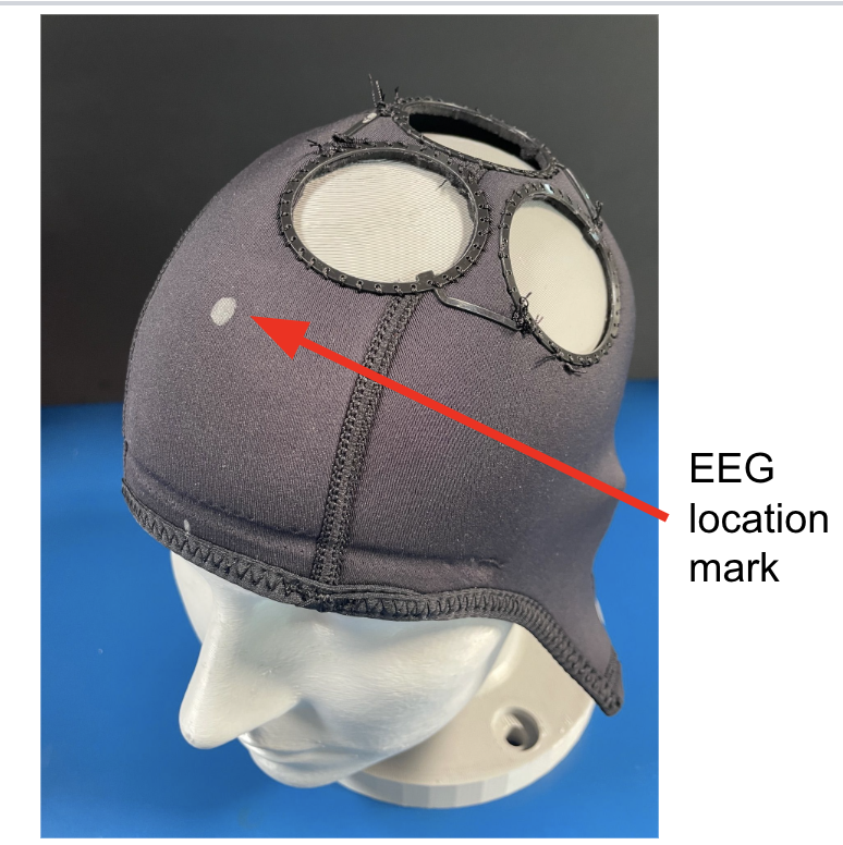
You may install EEG electrodes either before or after the optical modules. Begin by positioning the cap on your reference headform and marking all intended EEG locations.
For the most accurate layout, mark your EEG coordinates before cutting the larger optical module holes. If you are designing custom position guides in CAD, consider integrating the EEG cutouts directly into the guide file to ensure perfect relative spacing between sensor types.
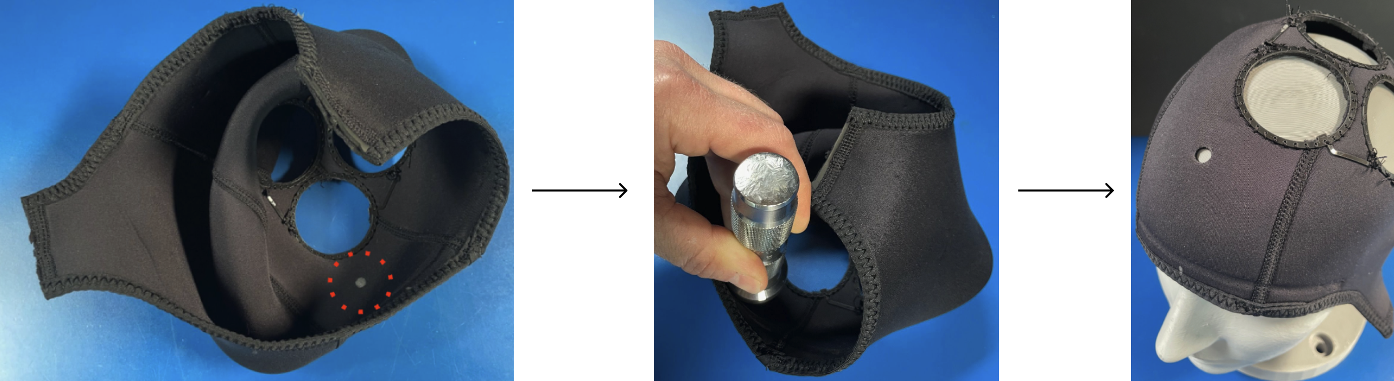
Ensure all optical modules and mounts are removed to provide a clear workspace. Using a 6mm (1/4") hole punch, create openings at each marked location.
If you are using a hammer-driven punch, flip the cap inside out before striking. This prevents the punch from accidentally catching or damaging the ear covers or internal seams. A sharp, decisive strike against a firm work surface will yield a clean, professional mounting hole with minimal fraying.
Installing Electrodes
This step can be performed even if optical hardware is already installed.
Insert the brass electrode snap from the exterior of the cap through the newly punched hole. Secure it from the inside by threading an EEG thumb nut onto the snap.
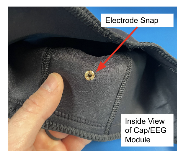
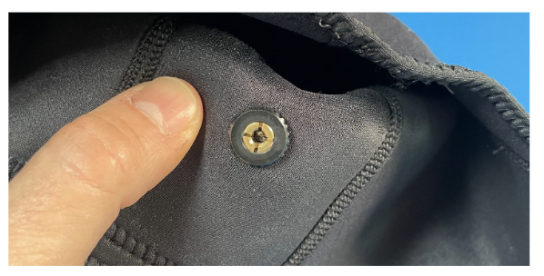
Use the Kernel-supplied Electrode Seating Tool to press the EEG electrode firmly into the brass snap (see Setting up the EEG Components). You should feel the electrode click into place, ensuring a stable electrical connection. Once all electrodes are seated, your multi-modal cap is ready for system connection and signal testing.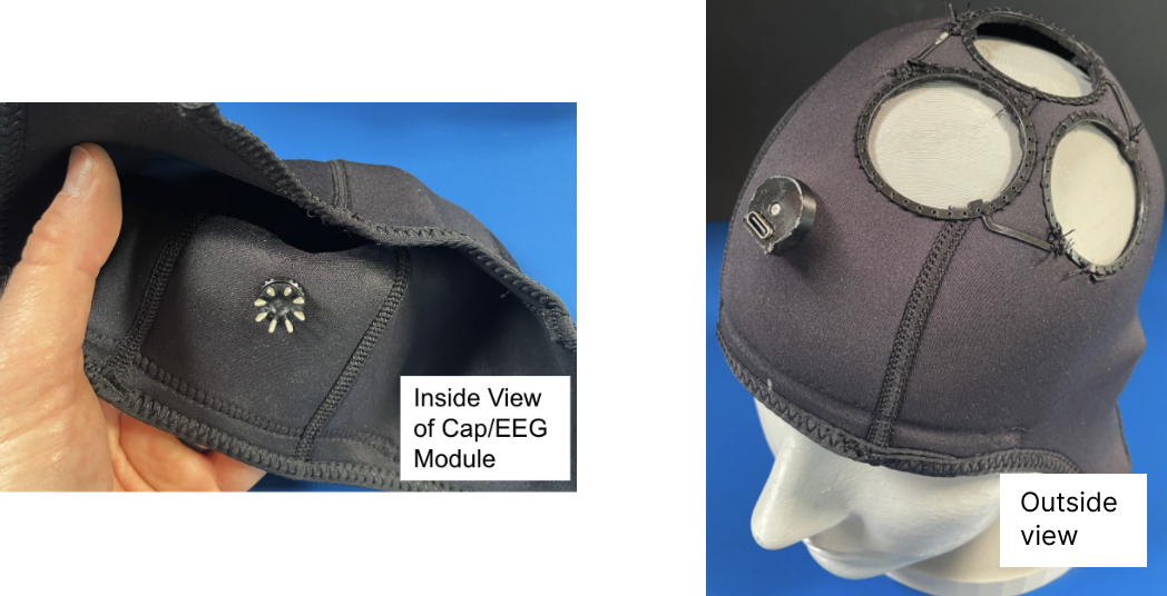
Chinstrap (Optional)
Required Materials
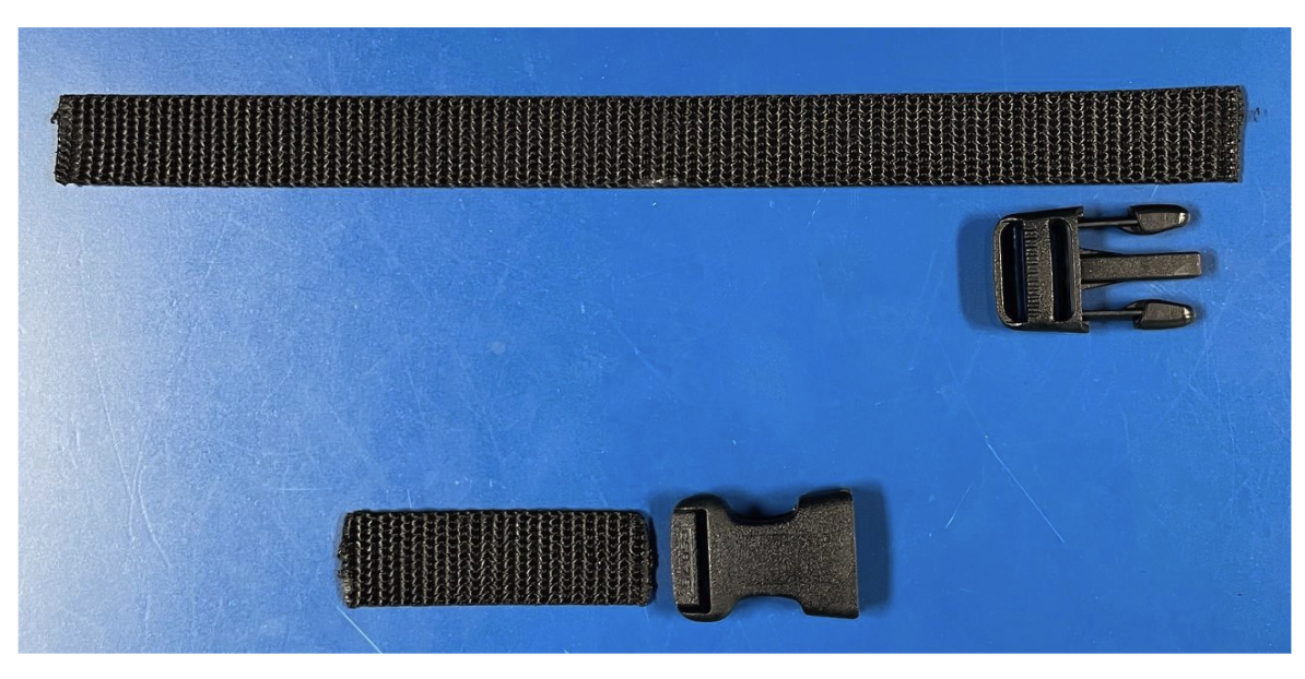
- Webbing: Sized to match your buckles (Nylon or Polypro).
- Side Release Buckles: One male and one female component (example here)
- Sewing Kit: Scissors, measuring tape, marker, needle, and T90 bonded nylon thread (example here)
- Optional: A lighter or small torch for heat-sealing edges.
Cut two pieces of webbing: one 24 cm, for the male side of the buckle and one 6 cm, for the female side of the buckle. If you have access to a heating device, melt the cut ends of the webbing with a flame to prevent fraying.
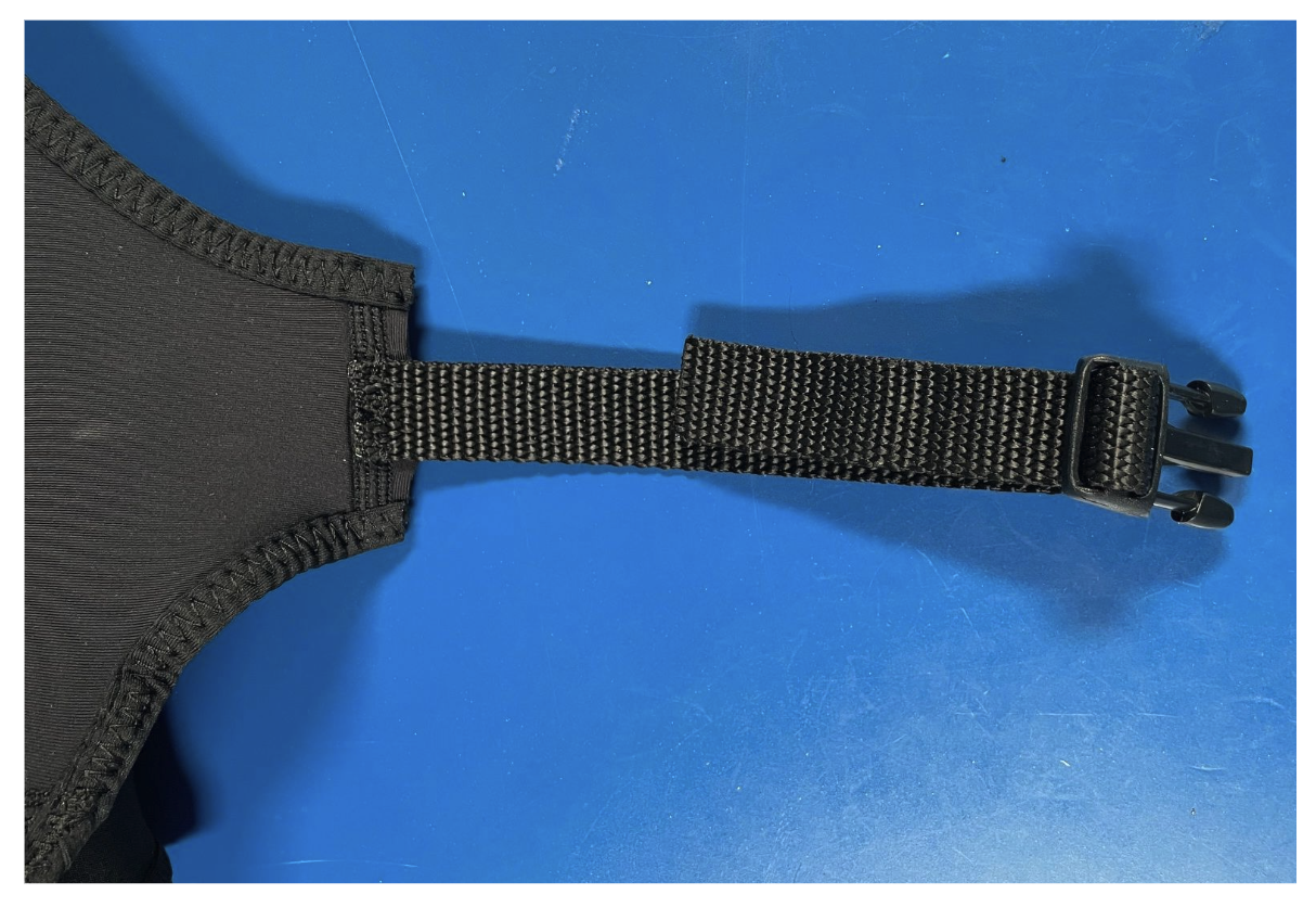
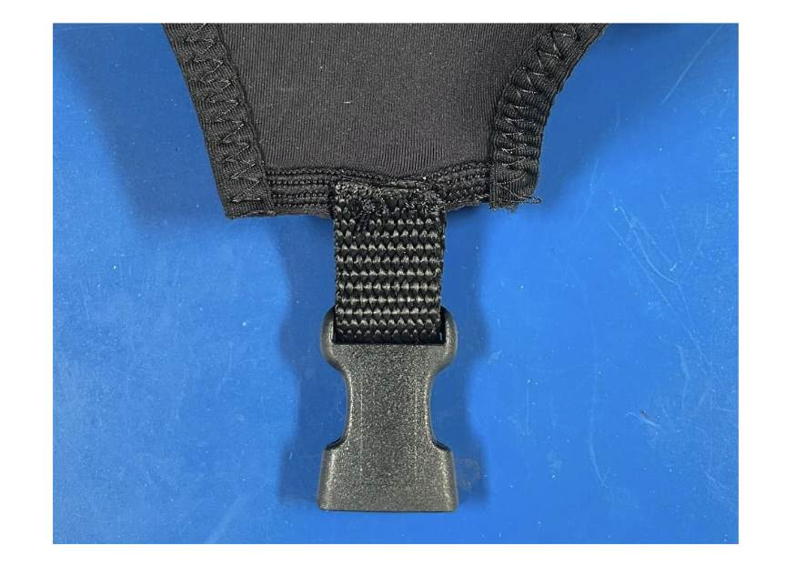
Fold the 6 cm webbing strip in half and thread it through the loop of the female buckle. Position the folded unit against the left ear flap of the cap. Secure it by stitching through both layers of webbing and the cap material. A backstitch is recommended here for its superior strength under tension.
Thread the 24 cm webbing strip through the ladder lock of the male buckle. Position the bottom "leg" of the webbing against the right ear flap of the cap. Stitch the webbing securely to the flap using a backstitch, ensuring the long tail remains adjustable through the buckle.