If your Organization ordered a Sync Accessory Box, it will be included with the Flow system. The Sync Accessory Box is a USB peripheral used for collecting data from external devices during the recording of a Flow recording. This might include devices like a button/trigger, eye trackers, VR/AR headsets, or physiological measurement devices (e.g. pulse oximeter, capnometer, respiration belt, etc.).
 You might also use the Sync Accessory Box to record Task data generated from certain external devices. You do not need to use the Sync Accessory Box to record or synchronize data from Kernel Unity Tasks, or Tasks created using Kernel's Task SDK (as long as your task-generating system is on the same local network and clock as the data acquisition computer). In those cases, Kernel's software automatically synchronizes and record those data along with your Flow data.
Sync data collected through the Sync Accessory Box is included in the dataset for each recorded session, and may be accessed in downloaded reports and dataset files. To learn more, see Downloading datasets.
Tasks involving the Sync Accessory Box include:
- Setup the Sync Accessory Box
- View the connections
- Connect an analog device
- Connect a digital device
- Viewing and sending signals
- Use the digital inputs to encode a signal
To setup the Sync Accessory Box:
- Connect the Sync Accessory Box to the data acquisition computer using the supplied blue USB cable.
View the Sync Accessory Box connections:
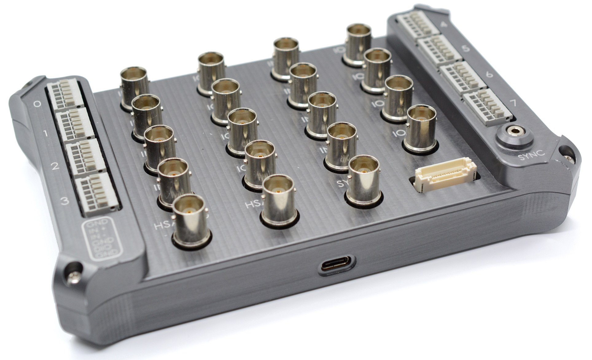
The Sync Accessory Box has eight digital, and ten analog I/O ports that can all be used simultaneously.
.jpg)
- The eight standard analog ports contain a positive (+) and negative (-) connector (use either BNC or bare wire. To learn more, see below.)
- Depending on the type of device you are using, you may use just the + (for single-ended) or use both connectors (for differential). When both connectors are used, the value used is the difference between the positive and negative values (the negative is subtracted from the positive).NOTE:The negative analog ports are designed to support both input and output (and so are labeled "IOn-"). Output will be supported in a subsequent release.
- If you configure a digital port as an output, it will generate a 3.3v signal.
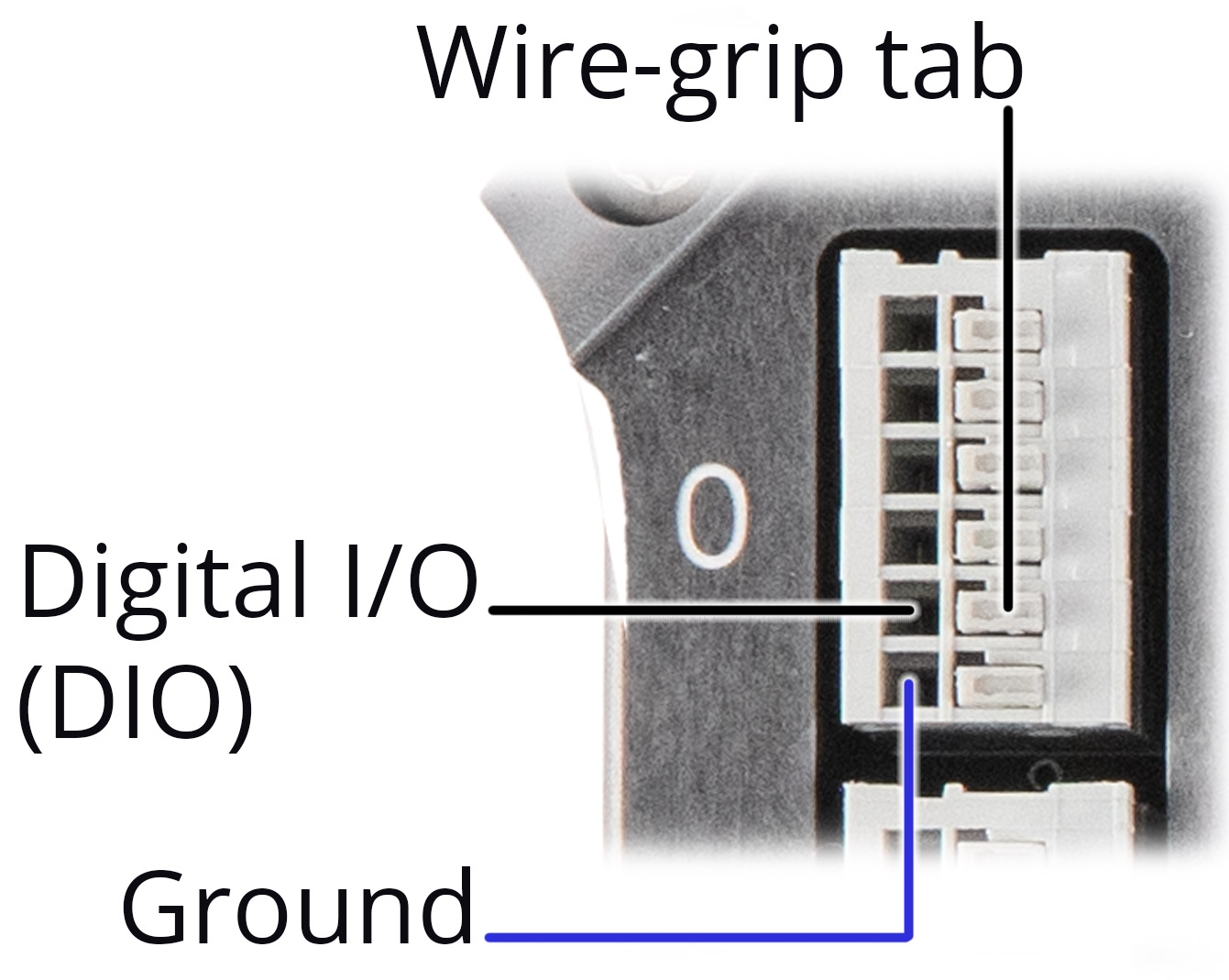
- Each terminal block contains both digital and analog ports:
.jpg)
(Manufacturer part number for Digital I/O mating housing: JST ZER-10V-S)
To connect an analog device:
Analog signals may be single ended (requiring one connector) or differential (requiring two connectors). When both connectors are used, the value used is the difference between the positive and negative values (the negative is subtracted from the positive).
- Connect the output of your external device to a channel on the Sync Accessory Box.
- Use either BNC connectors or plug bare wires/pins into the terminal block for the corresponding input number (0-7).
- Be sure to ground any incoming (bare wire) signals.
.jpg)
- Use one of the two high-speed analog (HSA) inputs for sources that require a higher sampling rate such as EEG, EOG, etc.
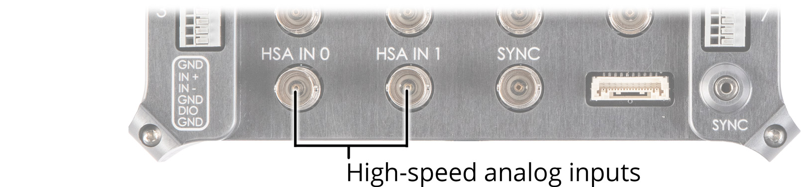
- Inputs 0 - 7 are sampled at 1 kHz (BNC or bare wire)
- Inputs HSA 0 and 1 are sampled at 10 kHz (BNC)
- Analog input voltage (with programmable gain set to 1):
- Single ended: -5 to +5V
- Differential: -5V to +5V
- HSA (single ended): 0v - 2.5v
Depress the tab again to release the wire.
To connect a digital device:
- Digital inputs can be plugged into the DIO slot of any of the terminal blocks on the Sync Accessory Box.
- Be sure to always ground any incoming sources.
- Any signal between 0v and .9v will register as "low" (0), any signal 2.3v to 5.3v will register as "high" (1).
Signals between .9v and 2.3v may not trigger either state, and should not be used.
Depress the tab again to release the wire.
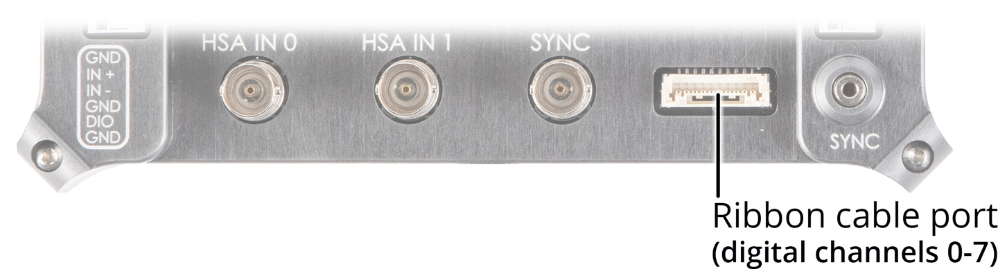
- You can also connect digital sources using a ribbon cable, which can contain up to all eight digital inputs/outputs at once. This may be helpful for using the digital inputs for encoding a 1-byte symbol.
Viewing and sending signals:
Contact Kernel Support to receive a custom SDK that will
- Display the ten analog signals in real-time
- Display the eight digital channels in real-time
- Allow you to set any digital channel to output 3.3v, which can be used to power a recording device like a PPG monitor, or to provide a signal to another device.
Disconnecting the USB cable from the Sync Accessory Box re-configures all channels to be set as inputs to minimize this risk.
To use the digital channels to encode a signal:
In some cases, you may want to use all eight digital channels to be treated as a single byte of data to be encoded and recorded with your Flow data.
- Connect pins to the DIO ports (or insert a cable to the Ribbon Cable port) on the Sync Accessory Box.
- Send a 1-byte signal from your data source encoded in binary where each of the digital channels represents a character in an 8-bit string:
- Digital channel 0 is the right-most value: XXXXXXX_
- Digital channel 7 is the left-most value: _XXXXXXX
The resulting symbols are recorded as sync data in the Flow session.